

 English
 русский
 Español
 中文简体
中文简体
Tower crane selection is rarely about choosing the largest machine available. The right choice depends on a single engineering value: the required load moment (TM). This value determines whether a crane can safely handle the heaviest load at the farthest radius your project demands.
Load moment, measured in ton-meters (TM), combines lifting capacity with reach. It is the reference used by manufacturers, structural engineers, and project planners to compare crane classes, size foundations, and verify tie-in loads. Without a reliable TM calculation, even a well-funded project can end up with an over-specified crane that raises costs, or an under-capacity crane that stalls the schedule.
This guide explains what load moment means, how to determine the required load moment for tower crane selection, and how to apply the result when comparing different crane models.
Content
- 1 What Is Load Moment (TM) and Why Does It Matter?
- 2 How to Determine the Required Load Moment (TM) in 5 Steps
- 3 Worked Example: Calculating TM for a Precast Panel Lift
- 4 Five Factors That Change the Required TM
- 5 Common Mistakes to Avoid When Selecting by TM
- 6 Frequently Asked Questions About Load Moment (TM)
What Is Load Moment (TM) and Why Does It Matter?
Load moment is the product of the lifted load and its horizontal distance from the crane's axis of rotation:
A 4-ton load placed at a radius of 50 m, for example, produces a load moment of 200 TM. This single value captures both capacity and reach, which is why it appears so often in tower crane load charts and selection tables.
Manufacturers rate tower cranes by maximum load moment because it reflects real lifting capability better than peak capacity. A crane that lists 10 t maximum capacity may deliver that figure only at a short radius; at 60 m the same machine might handle just 4 t. If your project requires 6 t at 50 m, peak capacity alone will mislead you.
During selection, the required TM becomes the baseline. Every candidate crane must offer a load-radius curve that covers the heaviest load at every radius the project needs. If you are still building your selection framework, our heavy construction tower crane capacity selection guide explains the wider planning process in more detail.
How to Determine the Required Load Moment (TM) in 5 Steps
Step 1: Identify the Heaviest Lift
List every prefabricated element, machine, or material bundle that will be lifted. Add the weight of the lifting accessory, such as spreader bars, slings, and hooks. The heaviest combination, not the heaviest single part, becomes the design load.
Step 2: Define the Maximum Working Radius
Measure the horizontal distance from the crane's rotation center to the farthest pickup or placement point. Include the building footprint, obstacles such as adjacent structures, and the crane's own position. The governing radius may not be the jib tip: a load lifted close to the mast on a tall building can still create a large moment after the crane climbs through multiple levels.
Step 3: Calculate the Required TM
Multiply the design load by the maximum working radius:
If critical lifts happen at several radii, calculate TM for each combination and use the highest value.
Step 4: Apply a Safety Margin
Add a practical working margin of 10-15% to cover dynamic effects, wind, load chart tolerances, and site variables. Alternatively, divide the raw required TM by an efficiency factor of 0.85-0.90. This margin turns a theoretical requirement into a specification that remains safe under field conditions.
Step 5: Compare Against Manufacturer Load Charts
Read the published load chart for each candidate crane and verify that the moment capacity at the governing radius exceeds the required TM. Check several intermediate radius points, not just the jib end, because the capacity curve is rarely linear.
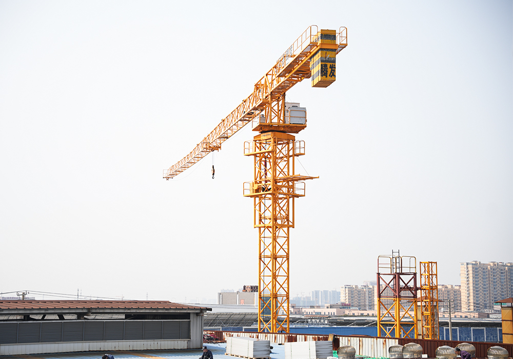
Long-jib machines illustrate this point. The flat-top series below offers a typical headline specification for matched capacity and reach.
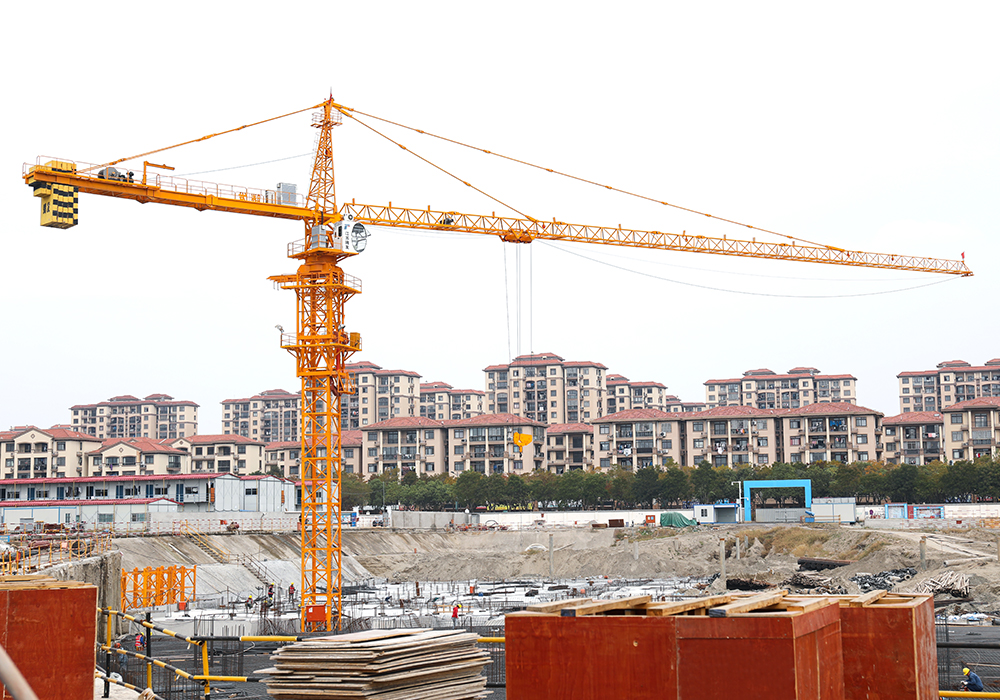
 QTP200(6030) Flat-Top Tower Crane with 60m JibWith a 10t maximum capacity, 60m radius, and 2000 kN·m rated moment, this flat-top model matches the long-jib specification discussed for verifying required TM before requesting foundation reactions.View Product →
When you compare figures like these against your calculated required TM, you can shortlist candidate models with confidence before requesting detailed foundation reactions.
Worked Example: Calculating TM for a Precast Panel Lift
A contractor needs to place precast concrete wall panels on a mid-rise building. The heaviest panel weighs 5.4 t, and the lifting accessories add 0.6 t, giving a design load of 6.0 t. The furthest panel position is 42 m from the crane rotation center, and after the final climbing stage the governing radius reaches 45 m.
Required TM = 6.0 t × 45 m = 270 TM. Adding a 15% safety margin:
Two candidate cranes are compared at the governing radius of 45 m:
| Candidate | Capacity at 45 m (t) | Moment at 45 m (TM) | Selection result |
|---|---|---|---|
| Model A | 6.4 | 288.0 | Rejected: below 310.5 TM |
| Model B | 7.2 | 324.0 | Accepted: above 310.5 TM |
Model B clears the requirement at the governing radius. A 12 t class crane with a 70 m jib provides this level of headroom comfortably:
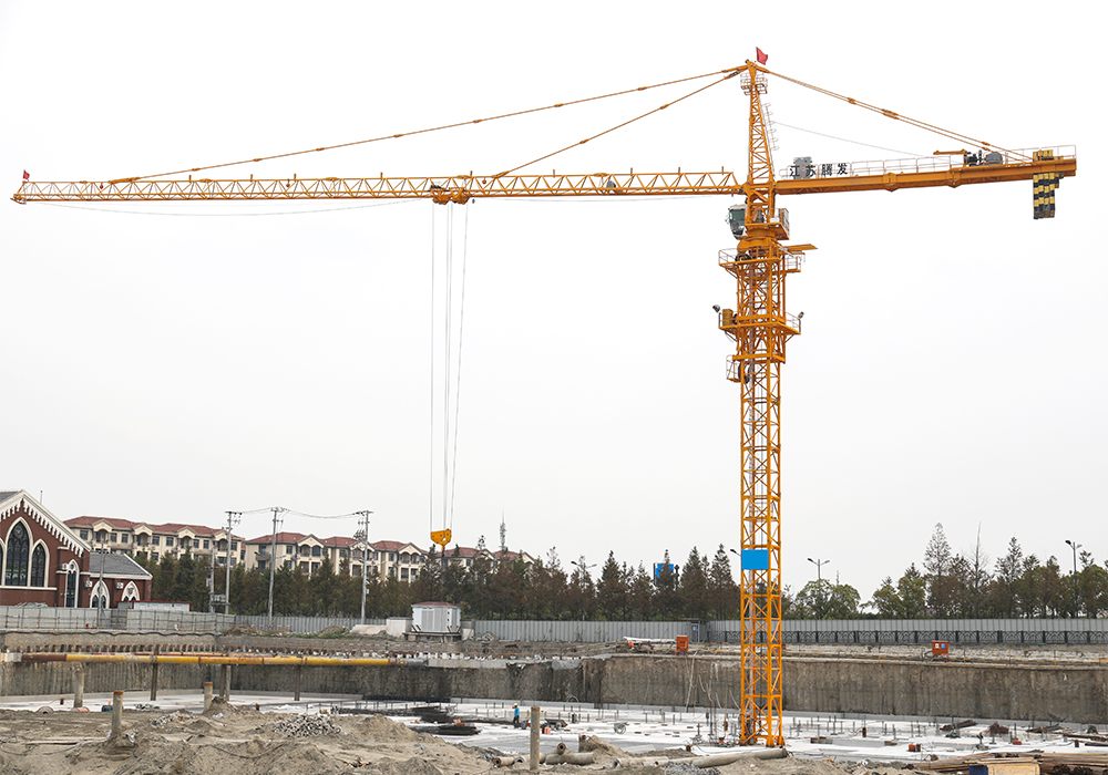
 QTP160(7015) Topless Tower Crane with 70m JibOffering 12t capacity at a 70m working radius, this topless crane provides the headroom needed for the governing-radius check, making it a strong candidate for lifts beyond 45m.View Product →
Repeat the check at every radius where a significant lift will occur, not only at 45 m.
Five Factors That Change the Required TM
- Foundation and anchorage. The load moment flows directly into the foundation. A higher TM requires a larger counterweight block, deeper piles, or additional tie-in levels, so early TM values directly affect civil works cost.
- Climbing sequence. When the crane rises with the structure, the radius to certain loads can increase at each stage. Recalculate TM after every planned climb.
- Building geometry. Setbacks, roof overhangs, and temporary structures alter the practical radius. A 3D model check of the crane position is the most reliable way to identify the governing radius.
- Wind and dynamic loads. Strong wind reduces the usable capacity of the crane and effectively increases the required TM during exposed lifts. Apply the local derating table when the site is open or coastal.
- Staged or multi-crane lifting. Dividing a heavy component between two cranes changes the load path and the moment on each machine. The calculation must be repeated for the load share each crane actually carries.
For sites where the working radius must be reduced to avoid obstacles or neighboring cranes, a luffing jib configuration is often a better match:
 QTD80 Luffing-Jib Tower Crane with 40m JibIts adjustable jib angle allows rapid radius reduction, suitable for confined urban sites where obstacles or neighboring cranes demand a smaller operating radius and lower governing moment.View Product →
With an adjustable jib angle, the luffing type trims its operating radius quickly, which can reduce the governing TM in confined urban sites.
Common Mistakes to Avoid When Selecting by TM
- Selecting on peak capacity. A 10 t maximum rating means nothing if the heaviest lift occurs at 60 m radius. Always compare moments, not headline tonnage.
- Forgetting lifting accessories. Spreader beams and hooks can add several hundred kilograms to the design load. Omitting them understates the required TM.
- Checking only the jib end. Load moments must be verified at multiple radius points because the capacity curve drops faster toward the tip.
- Ignoring wind derating. In coastal or open sites, wind can reduce the allowable load by 10-20%, which directly increases the practical required TM.
- Skipping the safety margin. A bare calculation without margin leaves no room for site variables, dynamic swing, or load chart tolerances.
A documented TM calculation also helps when several stakeholders review the crane plan, because every downstream decision can reference the same baseline numbers.
Frequently Asked Questions About Load Moment (TM)
Q1: What safety margin should I apply to the calculated TM?
A margin of 10-15% is common for most building sites. For coastal, high-wind, or precision-heavy lifting, use a higher margin and consult the crane manufacturer's derating tables. The margin converts a theoretical capacity into a dependable site specification.
Q2: Should I calculate TM for every lift or only the heaviest one?
Calculate TM for every critical lift. A moderately heavy load placed far from the mast can produce a larger moment than the heaviest load lifted close to the mast. The governing case is the maximum moment combination, not the maximum weight.
Q3: How does TM relate to the kN-m values used in some load charts?
One ton-meter equals approximately 9.81 kN-m. If a manufacturer publishes the rated moment in kN-m, convert both sides of your comparison to the same unit before shortlisting models.
Determining the required load moment (TM) before contacting a supplier is the surest way to keep tower crane selection objective. Identify the heaviest lift, establish the governing radius, apply a realistic margin, and verify every candidate against load charts rather than catalog headlines.
Manufacturers publish load-radius curves precisely for this purpose. If you are comparing machines from different structural families, such as topkit, flat-top, and luffing jib tower cranes, the same TM calculation remains valid for all of them.